While trying to understand and tie the TCP/IP stack together I though it would be helpful to run through a simple scenario:
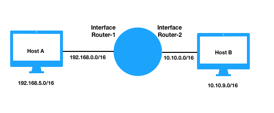
Host A is at 192.168.5.0/16 and Host B is at 10.10.9.0/16 and they are connected by a router where Router-1 is the interface connected to 192.168.0.0 and Router-2 is connected to 10.10.0.0.
Let’s say Host A sends Application layer data to Host B via UDP
Step 1) Host A’s application passes the data off to the layer-4 UDP module where it is encapsulated and a UDP header is added. The UDP header contains four 16 bit fields,
-UDP Source Port: an optional protocol port number that specifies to which port the reply should be sent, can be thought of as an identifier and is a pseudo random number.
-UDP Destination Port: specifies the port number for the receiving application. The protocol software at the receiving host uses the port number to demultiplex datagrams and pass the data to the application to which it has been sent(eg DNS on port 53).
-UDP Message Length : contains the total number of bytes in the datagram.
-UDP Checksum: The checksum is calculated on the UDP length, a protocol type code and the source IP address and destination IP address from the IP header.
Step 2) Host A’s UDP module passes the datagram to the layer 3 Network module where it is encapsulated and an IP Header is added. Some of the fields in the IP header include,
-Source IP address: specifies the original source IP address and can be changed if NAT is required. At this point it is 192.168.5.0/16
-Destination IP address: immutable and specifies the ultimate destination IP address, 10.10.9.0/16
-Total Length: The packets total length.
-Protocol: Specifies the format of the payload area and the number 17 is used for UDP.
-Time to Live (TTL): a number that specifies the maximum number of networks the packet can traverse and each router decrements the TTL by one and will discard the packet when it equals zero.
-Header Checksum: is used by the receiver to check the integrity of the header.
-Flags: the IP module can perform fragmentation of datagrams if the Application has created a message that is to large for the underlying network. The flags field contains a bit that specifies wether or not the datagram is complete.
Step 3) Host A’s IP module passes the packet to the layer 2 Data Link module where protocols such as Ethernet 802.3 format the packet into a frame. A header and a footer is added to frame the packet. The Ethernet header and footer fields include,
-Destination Address: 48 bit MAC address of the destination resolved with ARP, see below.
-Source Address: 48 bit Mac address of the source in this case MAC-Host-A.
-Frame Type: specifies type of data carried in the frame, in this case it would be set to 0x0800 for IPv4.
-Cyclic Redundancy Check (CRC): used to check for transmission errors
-Preamble: 7 bytes of alternating 1 and 0 bits
-Start frame delimiter: 1 byte value that marks the end of the preamble
At layer 2 the frame is addressed to the next hops physical MAC address. The Address Resolution Protocol (ARP) is used to resolve IP addresses to MAC addresses and the software maintains a table of recent bindings. Using the IP address and subnet mask of source and destination a determination is made wether or not the destination is on the same network as the source and in this case it is not. So the MAC address for the default gateway is used for the destination address of the frame. If host A does not have the MAC of the Router in it’s ARP table it will perform an ARP request and the frame will be addressed to MAC-Router-1.
Step 4) Host A’s Data Link module passes the frame to the layer 1 Physical module where the bitstream representation of the frame is transmitted over a physical data link and could be an RF signal, a voltage or photons. On 802.3 the NIC uses the carrier sense function to listen to the ether and if it is not busy it sends the frame, if no collision is detected host A assumes the transmission was successful.
Step 5) The frame will arrive at the Router-1 interface and if the CRC passes it will be passed from layer 1 up to the layer 2 Data Link module. The frame will be un-encapsulated, that is the ethernet header and footer will be removed.
Step 6) The routers Data Link module passes the packet up to the layer-3 Network module. The Router-1 interface will see that the destination IP address of the datagram does not match its own. The router will parse its routing table and find the network address matches a directly connected network. The router will switch the packet to interface Router-2 and if the packet does not need to be fragmented for transmission through the 10.10.0.0/16 network the IP packet will remain unchanged.
Step 7) The Router-2 Interface Network module passes the packet to the layer 2 Data Link module where the steps as outlined in Step 3 will occur but MAC-Router-2 will be used for the frames source address and MAC-Host-B is used for the frames destination address, resolved with ARP if required.
Step 8) Router-2 Data Link module passes the frame to the layer 1 Physical module where the bitstream representation of the frame is transmitted over a physical data link.
Step 9) When the bits arrive at Host B interface the NIC locks onto the preamble and start of frame delimiter and reads the MAC address. If the MAC address matches it own it reads in the frame and passes it up to layer 2. If the address does not match it drops the frame.
Because the networks are directly connected by the router I don’t think NAT or PAT is required when the packet is sent from Router-2 to Host B. But if Host B was not on a directly connected interface then the private source IP and Port of Host A would be mapped to the Router-2 IP and a Port, further the IP packet’s Source IP would be changed from that of Host A to the IP address of Router-2 and because the IP datagram has no port field, the PAT implementation will also need to modify the layer 4 header and rewrite the port number to a port number selected by Router-2.
It’s also interesting to note the fuzzy Layer boundaries with ARP and the UDP checksum.
Reference
Comer, Douglas E. Internetworking with TCP/IP Principles, Protocols and Architecture, 6th Edition, 2014