Summary
The Gate Mate can operate your gate or garage using voice commands or automatically with geofencing or at the touch of a button. Gate Mate consists of two major components, the App and the Hardware.
The hardware is made up of two ESP8266 micro controllers and a camera. The Arducam camera and one ESP8266 handle the video stream and the other ESP8266 coordinates the camera articulation, button push and communication with the App. The entire system really is like a symphony of radio waves and electrons, working in perfect harmony, to operate your gate or garage door.
The iOS Gate Mate App, sorry no Android just yet, can connect to the hardware from anywhere in the world which is really very handy if you need to open the gate when you are not at home or would like to view the video stream.
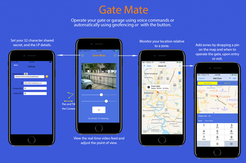
Many different frequencies and protocols are used with automatic and remote controlled (rc) gates and garages. In this project we utilise your existing remote control and an opto coupler to emulate the button press. Most remotes use security measures to prevent attacks where the code is captured and played back. We also use a pretty awesome encryption and authentication scheme to secure and authenticate the communication from the App over the internet, through your home network and to the Gate Mate hardware.
These are the highlights
- An ESPino (ESP8266) and PC817 Opto-Coupler are used to emulate a button push on the rc.
- A Pan Tilt assembly is used with the camera so that the point of view can be adjusted.
- An Arducam 2MP V2 Mini Camera Shield with ESP8266 Nano Esp-12F is used for the video feed to the iOS App.
- Communication between the ESPino, Arducam Nano and the App is done using HTTP.
- Router configuration including LAN Static IP’s and NAT Port Forwarding along with a DDNS or a Static IP is required.
- AES CBC Encryption and HMAC SHA256 is used to secure and authenticate communication.
- Voice recognition can be used with the commands “open”, “stop” and “close”.
- A geofence can be used to automatically open or close the gate or garage.
- The existing remote control is used.
- All the code is provided at the Gate Mate Github
Encryption
The encryption scheme involves using AES CBC and HMAC SHA256 for secure communication and authentication. A 32 character passphrase is required in the App and .ino file and of course they must match.
Components List
Notes-
-
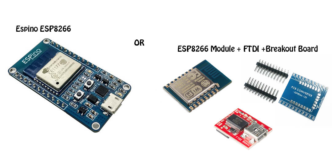
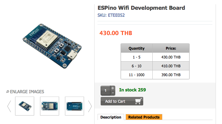
The Espino is used because it is ready to plug into a breadboard and comes with a micro USB (comms and power). You could just buy the ESp8266 module but you would have to mount it on a breakout board and use an FTDI for comms and power.
-
The Arducam 2MP V2 Mini Camera Shield with ESP8266 Nano is used for the video feed.
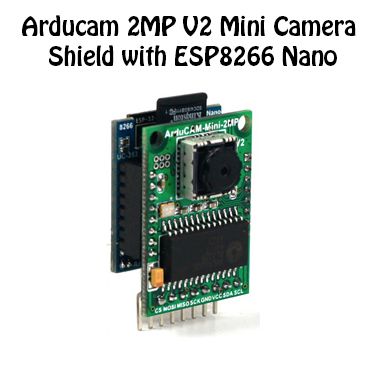
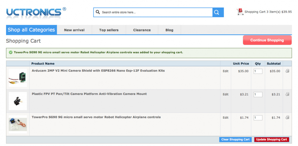
The major components came from UCTronics and Thai Easy Elec
http://www.uctronics.com
http://www.thaieasyelec.com/en/
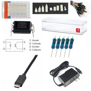
Other bits and pieces
- M3 PCB Standoffs
- Breadboard
- Clear Acrylic Case
- PC817 Opto Coupler
- 500 ohm Resistor
- Assortment of jumpers and wires
- 5V wall adaptor power supply
- Two micro usb cables
Network
To use the iOS App when not connected to your home network, that is when using cellular data or some other WiFi network, you will need to configure your router so that the traffic can get through to the correct device.
You will also need either a static IP, a DDNS service or be willing to update the IP entry in the App from time to time as your ISP changes your public IP address.
The router configuration is really quiet simple and involves assign static internal/private IP’s to both the Arducam Nano and Espino (the LAN part) and direct traffic on the assigned ports to the assigned IP’s (the NAT part).
For example in your router you set the static IP address of the Arducam Nano to 192.168.1.21 and then in the GateMateArduNano.ino file you set the webserver to port 83 (ESP8266WebServer server(83)), lastly setup NAT in your routers settings to forward any traffic on port 83 to 192.168.1.21.
For the ESPino you could set the static IP to 192.168.1.22, in the GateMateEspino.ino set the webserver to port 84 #ESP8266WebServer server(84) and setup NAT to forward and traffic on port 84 to 192.168.1.22.
Step by Step
-
If you want to set the IP in the App and forget about it you can either setup a DDNS service or contact your ISP and request a static public IP, they normally charge for that. I have used https://www.dynu.com and they are great for a free DDNS service.
-
Get the MAC address of both the Espino and Arducam Nano. You can set the SSID and Password in the .ino’s, let them connect to your home network and then through your routers advanced settings pages you can find the MACs
-
Configure your router to assign static IP’s to the Espino and Arducam Nano, specifically use the MAC addresses to create Static IP entries in the LAN setup page.
-
Configure your routers NAT to port forward to your Arducam Nano and Espino so they can be accessed from the internet using your ISP assigned public IP address. When connected to your private network, the Arducam Nano and ESPino will have internal static IP addresses that are not visible from the internet. As above, the Arducam Nano is listening on port 83 and the Espino on port 84 (see this line in the respective ino files - ESP8266WebServer server(##). On the NAT setup page create entries so that any traffic on the assigned ports is routed to the correct static IP’s.
There are a lot of different routers and ddns services available so providing specific details is beyond the scope of this project. But if you just google NAT and LAN settings for your particular router and ddns services it should all be very straight forward and easy to set up.
Assembly
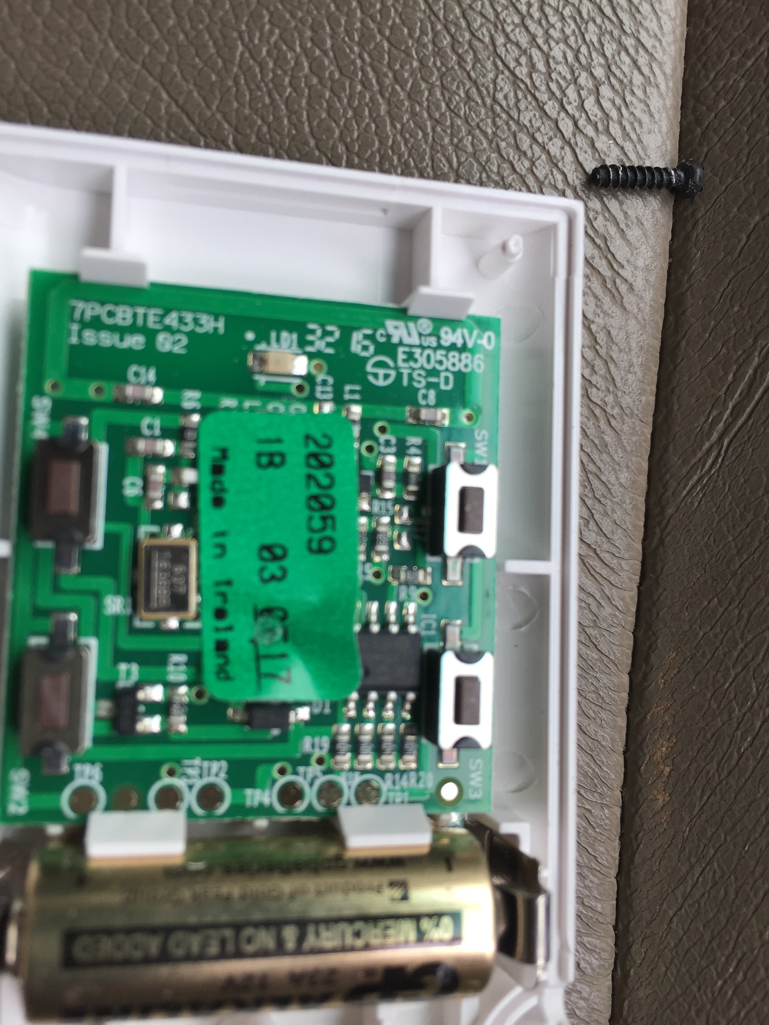
A button does one thing, it bridges a gap in the circuit to complete the electrical pathway. An optocoupler can be used to emulate the button and control a circuit that is completely isolated from your micro controller, in this case that is the remote control (rc) which has its own little circuit and battery.
The advantage of using an opto coupler here rather than, for example, a transistor is that we can keep the ground references, well the entire circuits for that matter, seperate. So we don’t need to worry about how to combine the ground of the rc with the ground of the ESP8266.
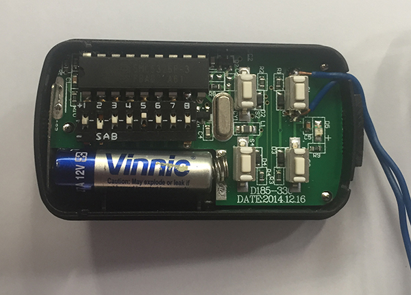
So the first thing to figure out is which side of the button should be connected to the PC817 collector and which side to the emitter. Open up your rc and using a multimeter to measure the resistance, figure out which side of the button is connected to the positive terminal of the battery. This high side will be connected to the collector which is pin 4 on the PC817.
Break out the soldering iron and
- Solder a wire to the high side leg of the button and connect the other end to the collector (pin4) of the PC817.
- Solder a wire to the low side leg of the button and connect the other end to the emitter (pin3) of the PC817.
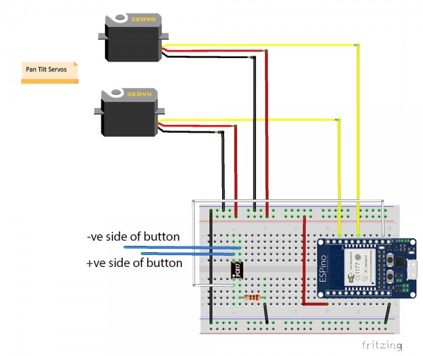
The last step for the opto coupler is to connect pin 4 from the ESP8266 to the anode (pin1) on the PC817 and connect the cathode (pin2) to ground through a 500 ohm resistor.
To check the pinout or any other specs here are the PC817 Specs PC817 Datasheet
Probably a good spot to include the pan tilt arm assembly pdf Pan Tilt
The rest of the connections are really straightforward, just refer to the fritzing and pictures below.
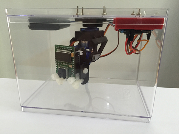
This is one way to lay out the case and breadboard.
Two micro usb cables have been cut down with the power and ground wires connected to the power and ground wires of a 5v wall adaptor power supply. One micro usb is connected to the Arducam Nano Camera and the other to the ESpino ESP8266.
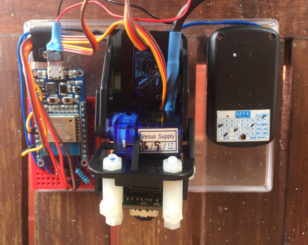
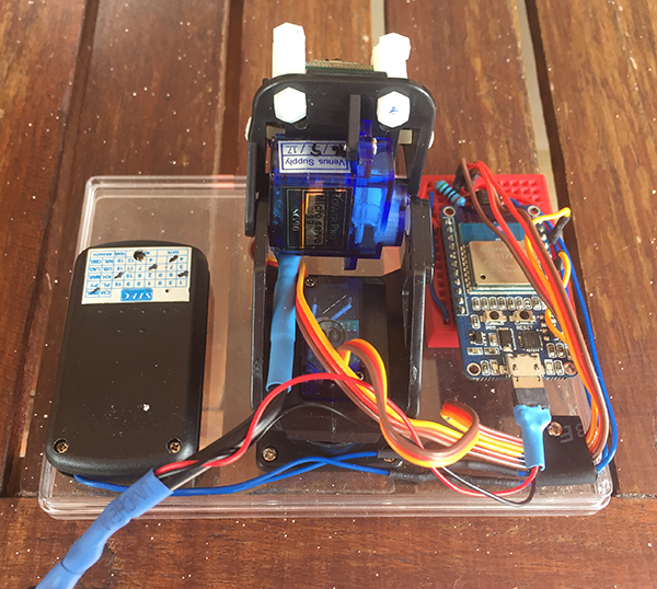
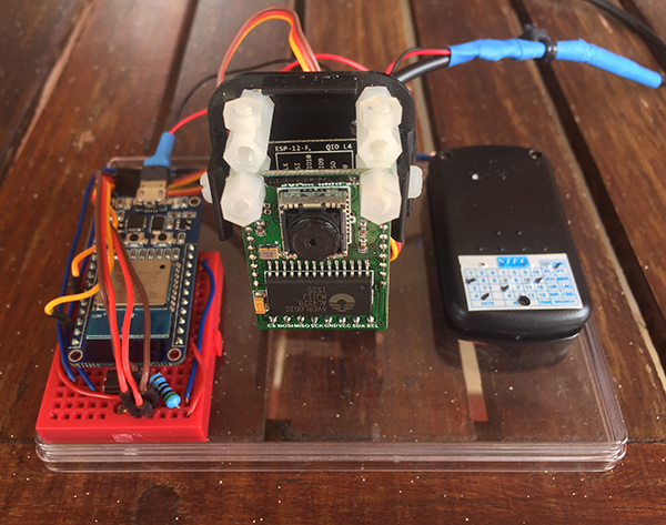
The finished case, the pan tilt assembly and the breadboard are secured to the lid using M3 stainless nuts and bolts, the rc is attached using double sided tape. A small hole is drilled through the button of the case to allow the power cable to exit and the case to sit flush up against a wall.
This is a close up of the wires attached to the rc button, quite simply a wire is soldered to both legs. When activated the current can flow through the opto-coupler instead of the button, emulating a button push, then the rc transmits its secure code to the electric motor to open or close the gate or garage.
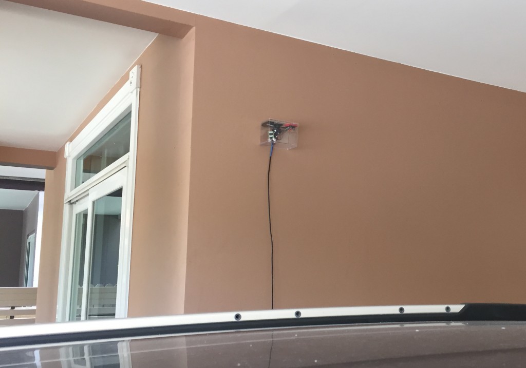
Using an anchor, masonry or otherwise, and with a small hole drilled in the acrylic case it can be attached to a wall facing the gate or the driveway or the garage door. Well really it can go anywhere so long as the remote control signal reaches the receiver at the motor.
That’s a wrap, feel free to drop me a message if you see something that could be improved or fixed or need something clarified.

